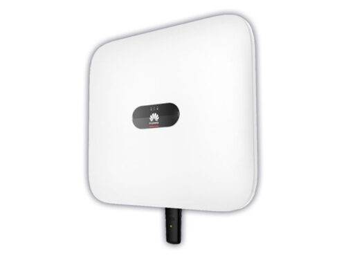
A grid-tie inverter converts direct current (DC) into an alternating current (AC) suitable for injecting into an electrical power grid, normally 120 V RMS at 60 Hz or 240 V RMS at 50 Hz. Grid-tie inverters are used between local electrical power generators: solar panel, wind turbine, hydro-electric, and the grid.
To inject electrical power efficiently and safely into the grid, grid-tie inverters must accurately match the voltage and phase of the grid sine wave AC waveform.
Some electricity companies pay for electrical power that is injected into the grid.
Electricity companies, in some countries, pay for electrical power that is injected into the electricity utility grid. Payment is arranged in several ways.
With net metering the electricity company pays for the net power injected into the grid, as recorded by a meter in the customer’s premises. For example, a customer may consume 400 kilowatt-hours over a month and may return 500 kilowatt-hours to the grid in the same month. In this case the electricity company would pay for the 100 kilowatt hours balance of power fed back into the grid. In the US, net metering policies vary by jurisdiction.
Feed-in tariff, based on a contract with a distribution company or other power authority, is where the customer is paid for electrical power injected into the grid.
In the United States, grid-interactive power systems are specified in the National Electric Code, which also mandates requirements for grid-interactive inverters.
Grid-tie inverters convert DC electrical power into AC power suitable for injecting into the electric utility company grid. The grid tie inverter (GTI) must match the phase of the grid and maintain the output voltage slightly higher than the grid voltage at any instant. A high-quality modern grid-tie inverter has a fixed unity power factor, which means its output voltage and current are perfectly lined up, and its phase angle is within 1 degree of the AC power grid. The inverter has an on-board computer that senses the current AC grid waveform, and outputs a voltage to correspond with the grid. However, supplying reactive power to the grid might be necessary to keep the voltage in the local grid inside allowed limitations. Otherwise, in a grid segment with considerable power from renewable sources, voltage levels might rise too much at times of high production, i.e. around noon with solar panels.
Grid-tie inverters are also designed to quickly disconnect from the grid if the utility grid goes down. This is an NEC requirement that ensures that in the event of a blackout, the grid tie inverter shuts down to prevent the energy it transfers from harming any line workers who are sent to fix the power grid.
Properly configured, a grid tie inverter enables a home owner to use an alternative power generation system like solar or wind power without extensive rewiring and without batteries. If the alternative power being produced is insufficient, the deficit is sourced from the electricity grid.
Grid-tie inverters include conventional low-frequency types with transformer coupling, newer high-frequency types, also with transformer coupling, and transformerless types. Instead of converting direct current directly into AC suitable for the grid, high-frequency transformers types use a computer process to convert the power to a high-frequency and then back to DC and then to the final AC output voltage suitable for the grid.
Transformerless inverters, which are popular in Europe, are lighter, smaller, and more efficient than inverters with transformers. But transformerless inverters have been slow to enter the US market because of concerns that transformerless inverters, which do not have galvanic isolation between the DC side and grid, could inject dangerous DC voltages and currents into the grid under fault conditions.
However, since 2005, the NFPA’s NEC allows transformerless, or non-galvanically isolated, inverters by removing the requirement that all solar electric systems be negative grounded and specifying new safety requirements. Amendments to VDE 0126-1-1 and IEC 6210 define the design and procedures needed for such systems: primarily, ground current measurement and DC to grid isolation tests.

